Electronics Installation and Operating Manuals

TK, TD, TX, and CC Audio Systems with or without iComm

Materials list:

You should have received the following items.


(2) Hovi Tips (aerators) with speakers, harness, and JST male connectors, (1) “Y” adapter cable with JST female and 3.5 mm audio connectors, (1) Amplifier, (1) Amplifier wall charger, (1) Omnidirectional Microphone, (2) Sealing tape - Clone Commander only.

Installation Instructions

  • Center Hovi tips in the helmet socket and mark the helmet or use pre-existing holes.
  • Drill or cut a 1/4” hole for the Hovi speaker harness, connector, and mount (if equipped).
  • Insert the Hovi Tip speaker harness through the hole.
  • Hovis without mount posts. Using E6000 or hot glue (CA glue not recommended), apply to Hovi or helmet. While being held in place, using painter's tape, secure until dry.
  • Hovis with mounting posts. Continue to press the mounting posts through the hole. Use the nylon lock clip to secure them to the helmet. Be careful not to pinch the smaller wires.
  • Connect the “Y” cable harness red connector to Hovi speaker harness red connector.
  • NOTE: They are NOT left/right specific.
  • Connect the opposite end of the “Y” cable (3.5 mm male audio plug) to the “speaker” port at the amplifier.
  • If you purchased a kit with the iComm voice modification box, using the provided 3.5 mm adapter cable, connect the iComm “output” port to the amplifier “mic” port.
  • Remove the headset microphone from the package. Install foam on the mic tip. If you purchased a kit with the iComm voice modification box, connect the headset mic 3.5 mm male to the “mic” port on the iComm. If your kit doesn't come with the iComm, plug the microphone connector into the “mic” port on the amplifier.
  • Install a headset mic on your head or secure the helmet. Note: For the system to function correctly and avoid feedback, the mic needs to rest firmly on your lips, directly in front of your mouth.
  • Using Velcro with adhesive (not provided) Velcro amplifier and iComm to helmet or other.
  • Test operation. Using the power/volume knob on the amplifier power system. Slowly increase the volume until the desired volume is achieved.

Additional Information

If you purchased a kit with the iComm, a PTT (Push To Talk) cable has also been provided. The PTT cable allows you to have control over your mic input. To operate, simply install the PTT cable (3.5mm jack) into the iComm “PTT” port. Turn on your amp. When the sleeved end is depressed, the mic will pick up and transmit sound. When released, the mic will not transmit.

The “AUX” port on the amplifier is for audio input. If you have an MP3 player (or another compatible device) capable of exporting audio, just into the AUX port via a 3.5mm male connector (not provided) and play music or TK chatter (found on the 501st website) through the Hovi Tips. Note: You'll have to have the PTT cable installed to prevent your imported audio from interrupting your voice.

NOTE: Like many other sound systems, the Hovi Speaker System is sensitive and is prone to feedback “screeching,” especially if the amp power is turned up too loud or there's not enough insulation between the Hovi tips and the microphone. Also, depending on the tone of your voice, you may have to remove the mic sock for the system to be loud enough yet not have feedback.

If you have further questions, please contact me at

[email protected] or on Discord

First Order TK Audio System

Materials list:

You should have received the following items.

Amplifier (1), Speakers with harness and connectors (2), “Y” cable (1), Speaker cloth (1), Omnidirectional Microphone (1), Rectangular insulating foam (2), Square insulating foam (1), Rectangular foam speaker risers (hollow in the middle) (2) Note: Only needed with the Anovos injection molded helmets

Installation Instructions

  • NOTE 1: If you have the Anovos injection molded helmet continue to step 1, all other helmets go to step 7.
  • NOTE 2: Trial installs all components before removing any glue backing and securing components.

Anovos injection molded helmets

  • 1 1. Install the supplied foam risers (1/4" foam block with rectangular hole). Remove the adhesive backing and place the risers' glue side down toward the raised tube vents. Note: The rectangular hole should cover the forward set of vent holes. Ensure the risers are sealed against the helmet. It doesn't have to be perfect.
  • 2 2. Place pre-cut speaker cloth material over the rectangle hole.
  • 3 3. Place the speaker over the cloth material directly over the riser hole. Note: The speaker wire lead should face the back of the helmet.
  • 4 4. Using one strip of the provided 5" insulation foam, remove the adhesive backing and cover 1/2 of the assembly lengthwise (front to rear of helmet). Afterward, install the second strip, this time slightly overlapping the other side. Note: Ensure the insulation tape is sealed to the helmet on all four sides, including the speaker harness lead. The tape needs to be secured as tight as possible to reduce any feedback.

Once the above is completed, go to step 10.

All other helmets

NOTE: If you have the Anovos fiberglass helmet, pull back the material exposing the tube vent holes, then continue.

  • 1 5. Place pre-cut speaker cloth material over the vent holes.
  • 2

    6. Install the supplied foam risers. Remove the adhesive backing and place the risers' glue side down toward the speaker cloth material. The rectangular hole in the risers should cover the forward set of vent holes.

    Ensure the risers are sealed against the helmet. It doesn't have to be perfect.
  • 3 7. Place the speaker over the riser hole. Note: The speaker wire lead should face the back of the helmet.
  • 4

    8. Using one strip of the provided 5" insulation foam, remove the adhesive backing and cover 1/2 of the assembly lengthwise (front to rear of the helmet). Afterward, install the second strip, this time slightly overlapping the other side. Note: Ensure the insulation tape is sealed to the helmet on all four sides, including the speaker harness lead. The tape needs to be secured as tight as possible to reduce any feedback.

    Once the above is completed, go to step 10.

Electrical Connections

  • 1 10. Connect the “Y” harness (female connectors) to the male speaker connectors.
  • 2 11. Connect the opposite end of the “Y” harness (3.5 mm connector) to the “speaker” port of the rechargeable amplifier. Note: The amplifier should already be fully charged.
  • 3

    12. Connect the omnidirectional microphone to the “mic” port on the amplifier.

    NOTE: It is recommended you secure the microphone to the interior of the helmet so it is in the same place every time.
  • 4 13. Secure the amplifier to the interior of your helmet. Note: Velcro is best suited (not supplied)

Set up & Operation

  • 1 14. Position the mic so that the mic sock is resting directly on your lips. This is for proper operation. Test before powering on the amplifier.
  • 2 15. Power on the amplifier by rotating the knob from the off position. Note: The knob is also the volume control.
  • 3 16. Adjust volume & test system.
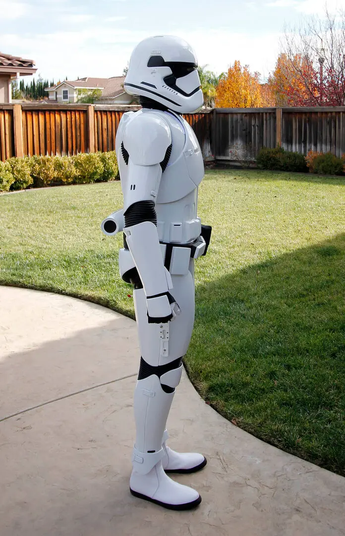
A person in a stormtrooper costume standing on the sidewalk.
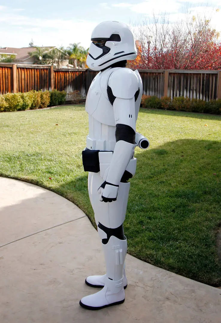
A person in a stormtrooper costume standing on the grass.

Additional Information

As mentioned above, using Velcro to secure the amplifier to the inside of your helmet is recommended but completely up to you.

The omni mic can be placed on your head, or you can use Velcro or others to secure it to the inside of the helmet. Regardless of the mounting position, the mic itself needs to be positioned close to your mouth for optimum operation and to help avoid feedback issues.

Anovos fiberglass helmets with insulation. After setup, re-secure (glue) helmet insulation back to the helmet, if applicable.

The “AUX” port on the amplifier is for audio input. If you have an MP3 player (or other compatible device), you can plug it into this port via a 3.5 mm male connector (not provided). Afterward, you can play music, TK chatter (contact me for files), or other audio through the audio system.

NOTE:
Like many other sound systems, the audio system is sensitive and is prone to feedback “screeching,” especially if the amp power is turned up too loud or there's not enough insulation between the speakers and the microphone. Also, depending on the tone of your voice, you may have to remove the mic sock to increase the output capability. If you still continue to have some feedback issues, add more insulation to the speakers, or your volume level may be too loud. If you have further questions regarding this please contact me at

[email protected] or on Discord

Biker Scout & Shore Trooper Audio System

Materials List:

You should have received the following items.


Helmet Snout with speaker and harness (1), Amplifier with wall charger (1ea), Extension cable (1), Omnidirectional Microphone (1)

Installation Instructions

  • The Hovi section comes painted because there is a speaker and speaker cloth directly behind the steel mesh. If painted over the existing paint, it may affect the speaker's performance or damage the speaker. If you choose to repaint this, do so at your own risk.
  • The engine and Hovi assembly are designed to be used with different helmet platforms. Using ABS plastic, you'll need to duplicate the engine baseplate that is not provided.
  • Once you've duplicated the baseplate, you need to select the engine location and drill a hole through the baseplate and helmet. Feed the snout speaker harness & connector through the holes.
  • You'll then need to secure the engine assembly to the baseplate with E6000 or similar. Once the engine glue has dried and the engine and backplate are reinstalled on the helmet, it is recommended you seal the space around the harness hole with duct tape or similar.
  • Connect the extension cable to the engine assembly harness.
  • Connect the extension cable to the amplifier “SPKR” port.
  • Connect the Omnidirectional microphone to the “MIC” port of the amp.
  • Power on the amplifier by rotating the on/off volume wheel and test.
  • Using Velcro (not provided), mount the amplifier in an area of your choosing.
  • Permanently mount the mic to the helmet using a tap or other. For optimum system performance, the mic should rest on your lips when the helmet is installed.
  • Recheck Operation.

Additional Information

The “AUX” port on the amplifier is for audio input. If you have an MP3 player (or other compatible device), you can plug it into this port via a 3.5 mm male connector (not provided). Afterward, you can play music, TB chatter (found on the 501st website), or other audio through the audio system.

NOTE:
Like many other sound systems, the audio system is sensitive and is prone to feedback “screeching,” especially if the amp power is turned up too loud or there's not enough insulation between the speaker and the microphone. Also, depending on the tone of your voice, you may have to remove the mic sock to increase the output capability. If you still continue to have some feedback issues, add more insulation to the front of the helmet speaker, or your volume level may be too loud.

If you have further questions, please contact me at 

[email protected] or on Discord

Death Trooper Audio System

Materials list:

You should have received the following items.

  • Amplifier with wall charger (1)
  • Speakers with harness and connectors (2)
  • “Y” cable harness (1)
  • Speaker cloth roughly 2" long (2)
  • Anker directional microphone (1)
  • 1/8" rectangular insulating foam 5" (2)
  • 1/4" rectangular foam speaker risers (hollow in the middle) (2)
  • Bluetooth MP3 player with USB charge/data cable and DT chatter files installed (1)
  • Bluetooth audio receiver with USB charge cable (1)
  • 1/4" clear round riser with self-adhesive (1)

Installation Instructions

NOTE: The helmet MUST be free of dust, oils, etc., for adhesive-backed items to stick to the helmet.

  • 1 1. If you have the Anovos fiberglass helmet, pull back the cloth material, exposing the tube vent holes. Any other helmet mfgs continue.
  • 2 2. Place a 2" swatch of speaker cloth over the tube vent holes. Note: The 1/4" risers are used to secure the cloth to the helmet. You may need to trim the cloth to within the border width of the risers.
  • 3 3. Remove adhesive backing from 1/4" risers and place over speaker cloth.
  • 4 4. Place speakers over the speakers over riser holes with the harness directed toward the back of the helmet.
  • 5 5. Place 5" rectangular insulating foam over the speaker and a 1/2” of harness lengthwise. Slightly overlapping the other section of insulation works best. Note: The goal here is to completely seal the speaker and harness to the helmet.
  • 6 6. Connect “Y” harness female connectors to male speaker connectors.
  • 7 7. Connect the opposite end of the “Y” harness (3.5 mm connector) to the “speaker” port of the rechargeable amplifier. Note: The amplifier should already be fully charged.
  • 8 8. Connect Anker directional microphone to the “mic” port on the amplifier.
  • 9
    9. Power the amplifier on by rotating the knob. The red LED will light up.
    Note: The knob is also the volume control.

NOTE: Test the system before continuing.

  • 1 A) Using Velcro or others to secure the amplifier to the inside of your helmet at a location of your choosing.
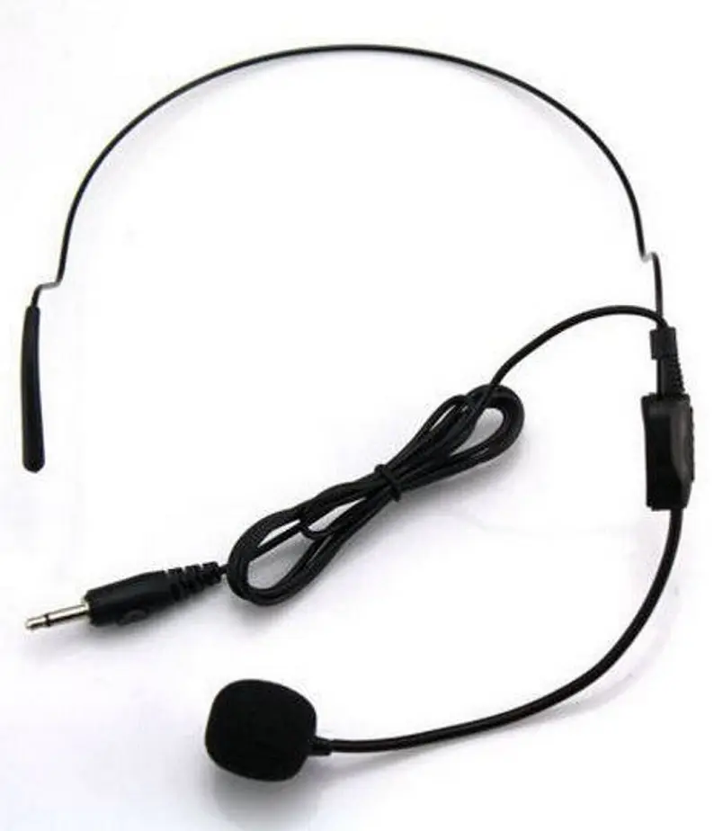
  • 2 B) The mic can be placed on your head, or remove the head wire and Velcro directly to the helmet. For optimum operation and help avoid feedback issues. The mic needs to be positioned with the white line (near the mic filter) close to your mouth.
  • 3 C) Test system (testing, testing, ck, ck). You should hear yourself out of the speakers.
  • 4 If all is well, re-secure (glue) helmet insulation back to the helmet, if applicable.

Installation Continued

  • 1 10. Install Bluetooth audio receiver (black box with 3" audio wire) by plugging in the 3.5mm male connector into the "AUX" port on the amplifier.
  • 2 11. Power on the receiver (For this portion, have your amplifier turned on and at roughly 3/4 volume). Depress the power button on the receiver for roughly 5 seconds. The LED will be a solid blue for a couple of seconds, then begin to flash blue. If you hold it longer than 7 seconds, the receiver will be placed in Pairing mode (flashing red light). If this happens, simply hold the power button again to power off, then retry. Once started, you'll briefly hear a musical note.
  • 3 12. Power on an MP3 player. Switch the power button to the "ON" position. Using the top menu button, navigate to "Bluetooth" and press the center (arrow) button. Allow the player to search for receivers. Once you see "LotFancy," highlight and press the center button. Afterward, you may be prompted to "Connect." If so, highlight and press the center button. Afterward, you should be taken to the audio file directory, where you should see two DT or Death Trooper audio files. Try both to see which you want to use.
  • 4 13. Set the Mp3 player and voice volumes. Everyone is different. Adjust to suit your needs. If you experience feedback, try adjusting the MP3 volume higher but lower the amp. Also, make sure your speakers are fully sealed. Note: A single self-adhesive clear riser, roughly 1/4" round, has also been provided. In the event you have difficulty operating the Play/Pause button with gloves on, trim the clear riser and then attach it to the MP3 Play/Pause button.

That's it! Velcro, all your items are in place, and you should be good to go. Enjoy!
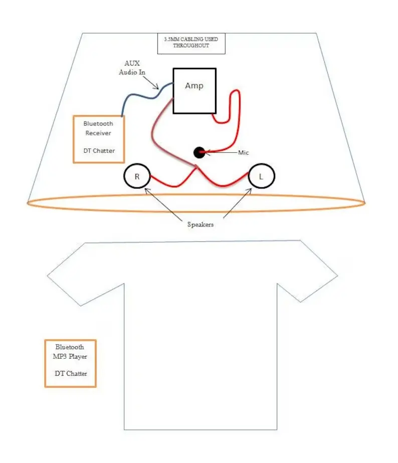
A diagram of the t-shirt with a wire attached to it.
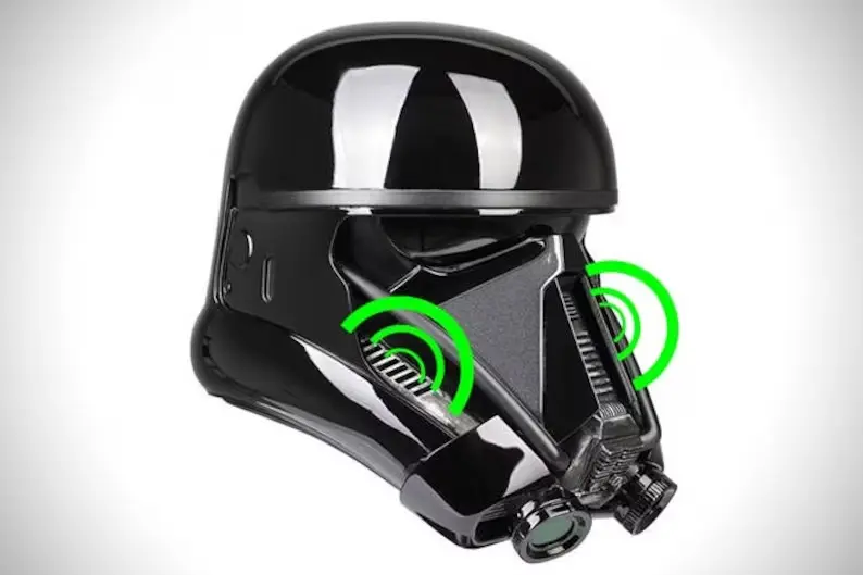
A black helmet with green circles around it.
A microphone and cord attached to a headset.

Additional Information

The audio receiver and MP3 player have been fully charged before shipping, and manuals have been included. If you have any issues with either, refer to the manuals. If you're still not having any luck, contact me at 

[email protected] or on Discord

Cooling System

Depending on what kit you purchased, you should have received one or more of the following items.

  • V1 – One piece kit consisting of two fans, harness, and battery box with on/off switch.
  • V2 – Two-piece kit consisting of two fans with a harness with a JST plug at one end and a power harness to connect the fan harness to a USB power source. The power harness connector consists of a JST and USB connector and an on/off switch.
  • V3 – Three-piece kit consisting of two fans with a harness with a JST plug at one end, a power harness, and a battery box with a harness.

Option Accessories

  • Harness “A” – Consisting of a power harness with a fixed 48” cable with an on/off switch.
  • Harness “B” - Consisting of a power harness with a detachable 48” cable with an on/off switch.
  • Velcro – Three 1”x 1-1/4” Velcro strips.

Installation and Operation

V1

  • A. Remove the battery box cover and install four AA batteries. Reinstall cover. Ensure nothing is obstructing fans. Using the on/off switch located on the battery box, power the fans on/off several times to ensure proper operation.
  • B. Install Velcro on the back of the fans and battery box. Note: Additional Velcro may be needed.
  • C. Mount the fans. The most common placement is at the lower front of the helmet.
  • D. Mount the battery box. The most common is at the back of the helmet.
  • E. Recheck System Operation.

V2

  • A. Connect the male JST connector (fan harness) to the female connector (power harness). Then connect the USB to your portable USB charger (DO NOT USE A WALL CHARGER!). Ensure nothing is obstructing fans.
  • B. If your charger automatically outputs power, then you should be able to toggle on/off the fan operation. If not, you’ll need to turn it on and recheck. Power the fans on and off several times to ensure proper operation.
  • C. Install Velcro on the back of the fans. Note: Additional Velcro may be needed.
  • D. Mount the fans. The most common placement is at the lower front of the helmet.
  • E. Mount the power harness or allow it to free float. The most common location is at the back of the helmet.
  • F. Recheck System Operation.

V3 – Power harness

  • A. Connect the male JST connector (Fan Harness) to the female connector (Power Harness).
  • B. Connect the USB to your portable USB charger. Ensure nothing is obstructing fans. If your charger automatically outputs power, then you should be able to toggle on/off the fan operation. If not, you’ll need to turn it on. Power the fans on and off several times to ensure proper operation.
  • C. Install Velcro on the back of the fans. Note: Additional Velcro may be needed.
  • D. Mount the fans. The most common placement is at the lower front of the helmet.
  • E. Mount the power harness or allow it to free float. The most common location is at the back of the helmet.
  • F. Recheck System Operation.

Battery Box

  • A. Connect the male JST connector (fan harness) to the female connector at the battery box harness.
  • B. Install four AA batteries. Ensure nothing is obstructing fans. Using the on/off switch located on the battery box, power the fans on and off several times to ensure proper operation.
  • C. Install Velcro on the back of the fans. Note: Additional Velcro may be needed.
  • D. Mount the fans. The most common placement is at the lower front of the helmet.
  • E. Mount the battery box. The most common location is at the back of the helmet.
  • F. Recheck System Operation.

Harness “B”

Harness “B” has an additional JST connector, enabling the user to disconnect the 48” optional harness with an on/off switch from the power harness.

  • A. Connect the female JST connector on the 48” harness to the male connector on the power harness.
  • B. Connect the male JST connector (Fan Harness) to the female connector (Power Harness).
  • C. Connect the USB to your portable USB charger. Ensure nothing is obstructing fans.
  • D. If your charger automatically outputs power, then you should be able to toggle on/off the fan operation. If not, you’ll need to turn it on. Power the fans on and off several times to ensure proper operation.
  • E. Install Velcro on the back of the fans. Note: Additional Velcro may be needed.
  • F. Mount the fans. The most common placement is at the lower front of the helmet.
  • G. Mount the power harness or allow it to free float. The most common location is at the back of the helmet.
  • H. Recheck System Operation.

If you have further questions, please contact me at

[email protected] or on Discord

SHA (Stormtrooper Hearing Assist)

Depending on what kit you've purchased, you should have received one or more of the following items.

  • SHA 5v - PCB with on/off switch, 2 pickup microphones attached to PCM via 15" leads, and a 6" 5v USB battery harness.
  • SHA 9v - PCB with on/off switch (located on a power cable), 2 pickup microphones attached to PCM via 15" leads, and a 9v battery box with on/off switch.
  • NOTE: Speakers are sold separately.
A pair of earbuds sitting on top of a floor.

Installation

Install pickup microphones (These are the small silver devices at the end of the cables)

  • Mounting Locations
    There are a few places where the microphones can be placed.
  • Option 1) Near the right and left side, the lower rim of the helmet. Use self-adhesive tape or Velcro to secure the mics. Avoid placing tape over the black-clothed area, as it will restrict hearing.
  • Option 2) Near the left and right side lower corners of the frown. Use self-adhesive tape or Velcro to secure the mics. Avoid placing tape over the black-clothed area, as it will restrict hearing.
  • Option 3) Behind the ears. For details on how to perform this step, please follow the link provided. Note that you will need an account to access the website. However, it's free. Please visit ... whitearmor.net. Scroll down to line 12.

Mount SHA PCB (5v and 9v)

  • The most common mounting location is at the back of the helmet. However, this doesn't always work for everyone, so find space available. Note: Use industrial-strength Velcro (not provided) to secure items to the costume.
  • SHA 5v is powered by a USB battery, so find a location where both will be within connecting harness proximity of each other.
  • SHA 9v can be powered off the audio amplifier battery or the optional 9v battery box. Regardless of which you choose to use, place both items within connecting harness proximity of each other. Note: 9v battery box will be installed with an on/off switch facing away from the costume. 9v battery can be installed before or after the battery box is installed.

Speakers (If equipped)

  • Speakers are most commonly installed so that they are literally touching your ears. If there's space between the speakers and ears, you may run into issues hearing properly. If this is the case, install fabric foam between the costume and the speaker.
  • Speakers come with self-adhesive on one side.
  • Once installed, plug the 3.5 mm male audio cable end into the SHA female out socket.

Earbuds (Not provided or sold)

  • Ear canal noise-canceling style earbuds work best for most individuals. If that's what you're using, then plug the 3.5 mm male audio cable end into the SHA female out socket. Install on the head, then install the costume.

Connecting power supplies and checking operations

  • 5v SHA - Connect USB harness male and female JST (red) connectors. Connect USB male to USB battery supply. Power on the battery, then power on SHA via the on/off switch located on the PCB. Note: Red LED will illuminate when on.
  • 9v SHA - There are two power options available with the 9v. If you have my audio system, the amplifier battery supply can be used to also supply power to the SHA. Simply connect the SHA white male harness connector to the white female connector on the bottom side of the amplifier. Note: the female connector can be seen when looking at the open end of the heat shrink (opposite side of the battery). Toggle the on/off switch on the SHA harness to power the SHA. Red LED will illuminate when on.
  • SHA 9v battery box - As mentioned earlier, once you've mounted the battery box, simply connect the male and female SHA and battery box harnesses. When the battery box is in the on position, the red LED light will illuminate the PCB.

Adjust volume

  • The aluminum post on the PCB is the volume control.
    Clockwise = Volume Up.

If you have further questions, please contact me at [email protected] or on Discord.